879
Solving double line to ground fault using the MVA method
Sequence networks of a power system can be so interconnected that solving the resulting network yields the symmetrical components of current at the fault. The connection of the sequence networks to simulate unsymmetrical double phase to ground fault is shown below:
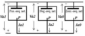
The sequence networks are indicated schematicaly by rectangles enclosing a heavy line to represent the reference bus of the network and a point marked P to represent the point in the network where the fault occurs. The positive sequence network contains emfs that represent the internal voltages of the machines.
If the emfs in a positive sequence network are replaced by short circuits, the impedance between the fault point P and the reference bus is the positive sequence impedance Z1 in the equation developed for faults on a power system and is the series impedance of the Thevenin equivalent of the circuit between P and the reference bus. When the other sequence networks are interconnected with the positive system network, the current flowing out of the network is Ia1 and the reference bus is Va1.
Since the reciprocal of positive sequence impedance Z1 is the short circuit MVA1 at unit voltage which flows through the sequence to a fault, we can replace the sequence network of Figure 1 with the corresponding MVA1, 2, 0 sequence equivalents, and use these to derive MVA equations for double phase to ground fault calculations. The connection of short circuit MVA equivalents of the Figure 1 sequence network shown below:
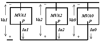
The resulting MVAF and IF for the two phase to ground fault can be determined by using Equations (1) or (2) respectively for components of equal or arbitrary X/R ratio. In case of equal X/R ratio, the equations read as follows:
Although the ARCAD online short circuit calculator doesn't currently calculate unbalanced faults all in one run, you can still use it to resolve positive, negative and zero sequence MVA SC required to determine total MVAF and IF at point of double line to ground fault. All you need is to develop hierarchical trees representing positive, negative and zero sequence networks of your power distribution system, program them into the calculator to determine the respective sequence short circuit MVA at prospective fault points. Short circuit current values for balanced three phase bolted fault as well as for unbalanced line-to-ground, line-to-phase etc. faults can be determined by substituting these calculated SC MVA values into the MVA to kA converter.
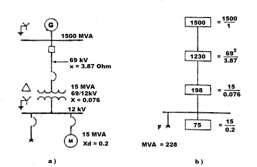
The example below shows how double line to ground fault is solved using the MVA method. Figure 3 represent one line (part a) and MVA diagram (part b) of simple power distribution system.
MVA sequence diagram below shows all components of positive, negative and zero sequence networks in SC MVA quantities. The connection shown illustrates double line to ground fault at the 12 kV bus.
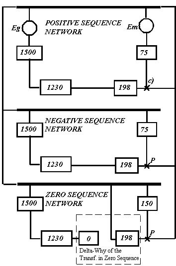
As noted, the three phase fault has been solved to be 228 MVA at the 12 kV bus. Since the positive sequence fault is equal to negative sequence fault, MVAX1 = MVAX2 = 228
The zero sequence fault MVA, however, must be calculated, and its MVA value then is combined with the positive and negative MVA values.
In our example, during a fault on the 12 kV bus only the transformer and the motor contribute to zero sequence MVAs. The delta primary of the transformer blocks any zero sequence power flowing from the system and across the transformer. Therefore, Figure 4 shows the zero sequence power circuit:
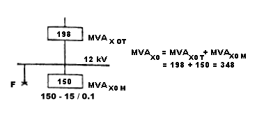
MVAX0 T = MVAX1 T = MVAX2 T = 198 as the transformer zero sequence reactance equals its positive and negative reactance.
MVAX0 M = 15 / 0.1 = 150 MVA, since the zero sequence reactance of the motor is about 1/2 of its positive sequence reactance. The total zero sequence fault power then is equal to the sum which is: MVAX0 T + MVAX0 M = 198 + 150 = 348
Assuming equal X/R ratios and substituting the above results for MVA0, MVA1 and MVA2 into our double phase to ground MVA equations, we get:
Copyright © 2019 ARCAD INC. All rights reserved.


