879
California State Professional Engineer Registration Examination
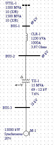
The following problem has been taken from the California State Professional Engineer Registration Examination of August 1965. The problem will be solved using the MVA method implemented in the online short circuit calculator presented on this web-site. Reactances are only used for practical purposes. Fault current values at buses 1, 2, 3 need to be calculated. The resulting short circuit current values will be compared with the respective values calculated using ESA Easypower 7.0.

MVA sequence diagram below shows all components of positive, negative and zero sequence networks in SC MVA quantities. The connection shown illustrates ground fault at node c ( Bus-3 above ).

Full scale short circuit study requires analysis of positive, negative and zero sequence networks. The table below shows the entry data required for the analysis. Note that all X/R values are assumed equal to 10 in this example, while resistances are practically ignored. This approach results in higher short circuit values, typicaly by 5 to 10 percent. Using such higher calculated values is considered safe. Accurate X/R should be used when available. Colored columns show the resulting MVA and X/R quantities for the respective sequences. See also What is the MVA method about for how the resulting MVA are calculated.

Table below is a compilation of the resulting MVA, X/R quantities as well as the system line to line voltages and fault resistances (default to zero) at potential fault points. These data are required for MVA to KA convertion. Note that only positive sequence MVA quantities and line-line voltages are required when only balanced 3 phase fault current values are needed.

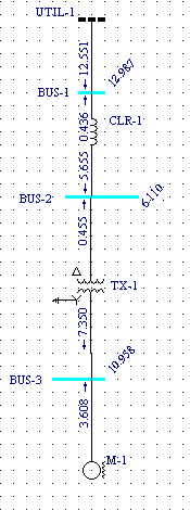
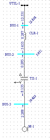
ESA Easypower 7.0 screen prints for our power system are shown below. These are presented here so one can compare the results produced by credible commercial software with the respective values obtained using our online short circuit calculator.


Table below is a compilation of the Easypower 7.0 calculation results (colorified in grey and yellow) with the online short circuit calculation results shown above them.

Industrial power system short circuits can also be solved using per-unit method. The figure below shows bus admittance and impedance per unit matrix for the above system. 1500 MVA and 69kV had been taken as base values.

The results of per unit calculations are equal to the MVA method values obtained by running the online calculator. Still, the MVA method does not require a common MVA base as required by the per unit method. Also, the conversion formulas used for the per unit method are more complicated and not easy to remember. Finally, the per unit method usually ends up with small decimals resulting from converting impedances from one voltage to another or from converting impedances to the same common base. Therefore, one can make mistakes in the decimals with resulting incorrect answers.
Following observation can be made from the above:
- Bolted 3 phase and line to line short circuit current values derived from Easypower and the Online Short Circuit Calculator presented on this web-site are by all practical means identical;
- Easypower uses same X'' = 20% subtransient reactance both for positive, negative and zero network calculations. This results in lower ground fault current values (Line-Ground and Double Line-Ground columns) comparing to those derived from the online short circuit calculator. The online calculator uses lower zero sequence subtransient reactance X''0 = 10% ( typicaly about 1/2 of motor positive sequence reactance ). It results in larger motor contribution and larger line to ground short circuit currents.
- The online calculator is suitable for impedance fault calculations. For example, arcing fault current values can be obtained when the arc impedance is known and substituted in the respective field of the MVA to KA converter.
Copyright © 2019 ARCAD INC. All rights reserved.


